Fieldbus Analyzer
Client
Fieldbus Diagnostics LLC
Competencies:
CPLD Design
Analog Hardware Design with SPICE Analysis
PCB Layout
Design a Protocol Analysis Tool for Foundation Fieldbus
There are still plenty of factories wired with Foundation Fieldbus as their control network protocol. And as some of them add devices — which may be on different protocols — the problem of looking at traffic becomes that much more acute. Additionally, Ethernet (particularly Industrial Protocol Ethernet) is becoming quite common in industrial settings. So our customer wanted a device that could be interrogated over an Ethernet link and would report network status via a connection to a host laptop (with Ethernet crossover cable) or via a web page served up with Apache.
Our job was to devise the circuit board with Foundation Fieldbus drivers and connectors on it as well as a link to a single-board embedded computer running a stripped down version of Linux.
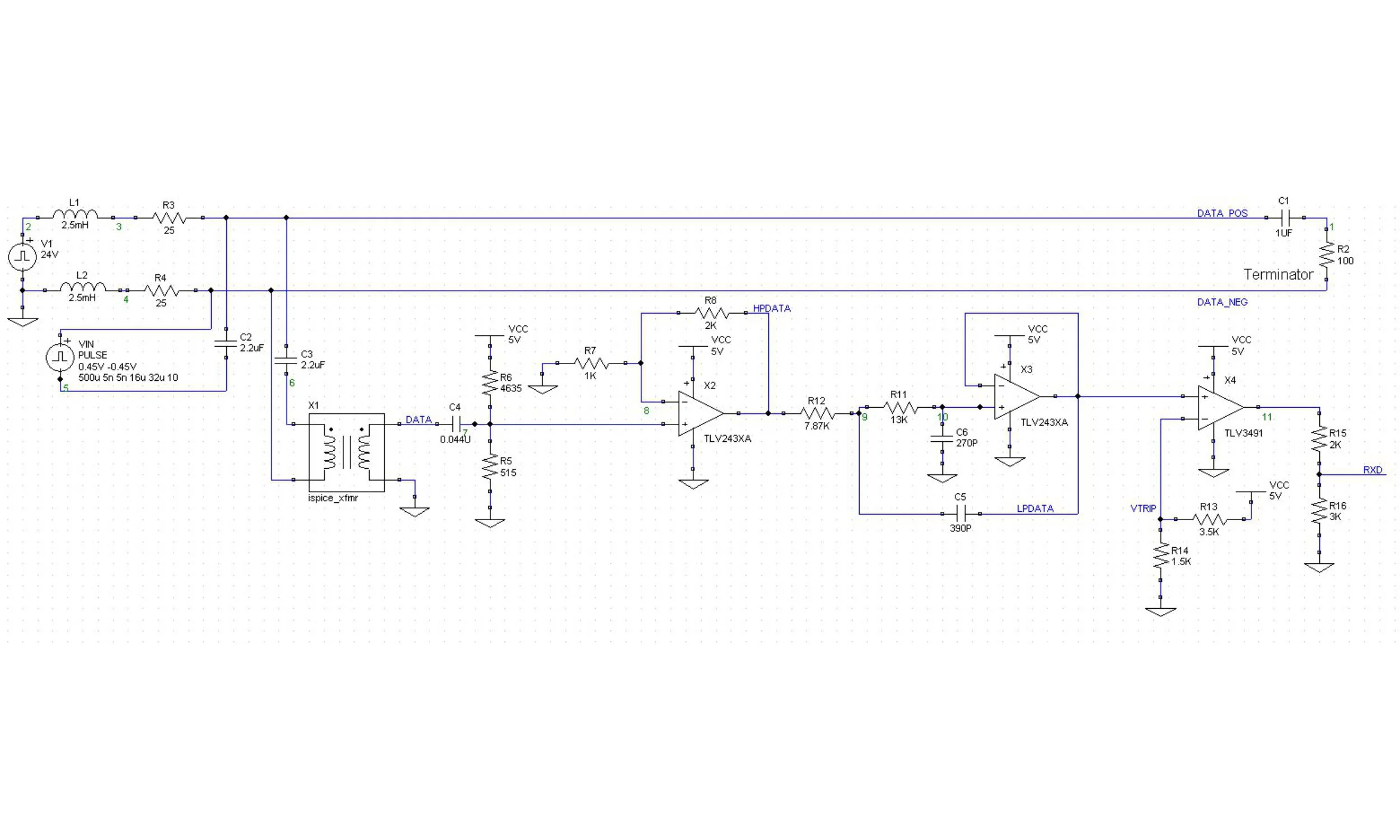
What We Did: Running TxD and RxD Analog Circuit Models in SPICE
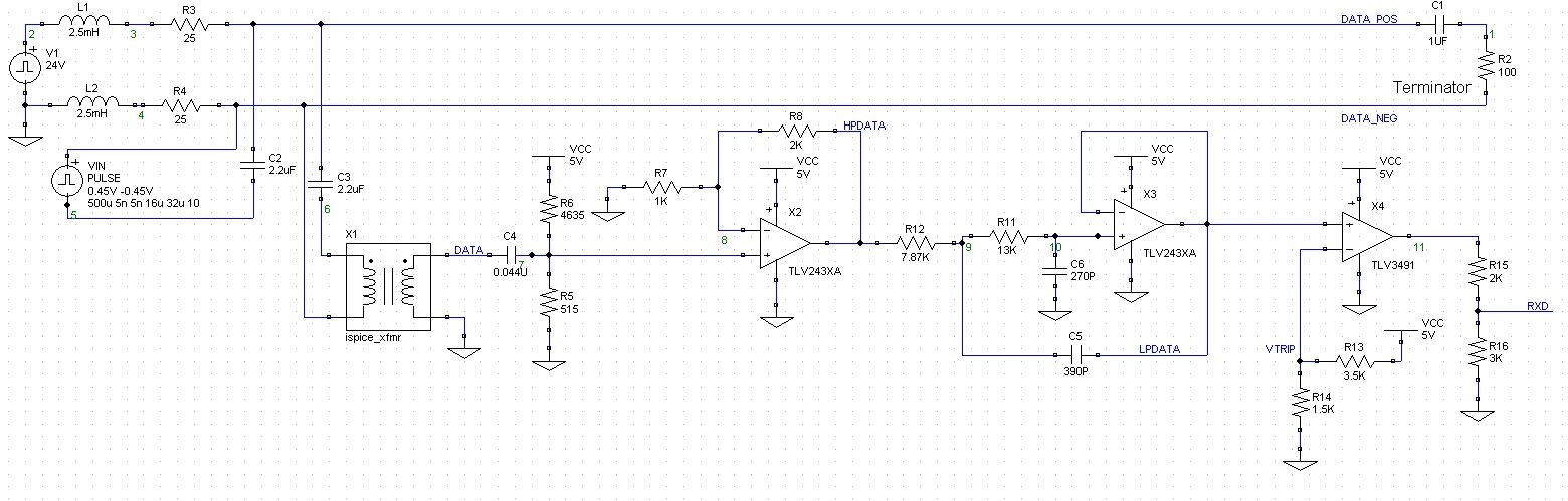
A bus like Fieldbus requires some modeling if it’s to be implemented correctly. And this includes checking pulse shapes on both the transmit and receive sides. Here is a SPICE model including AC coupling of an input signal, end-of-line termination, an impressed DC voltage for instrument power, and the lowpass and comparator circuits for pulse train recovery on the receive side. As one might expect, we implemented a similar circuit on the transmit side where the isolation transformer was driven from the secondary windings. And we combined the two models to completely model the entire PHY layer.
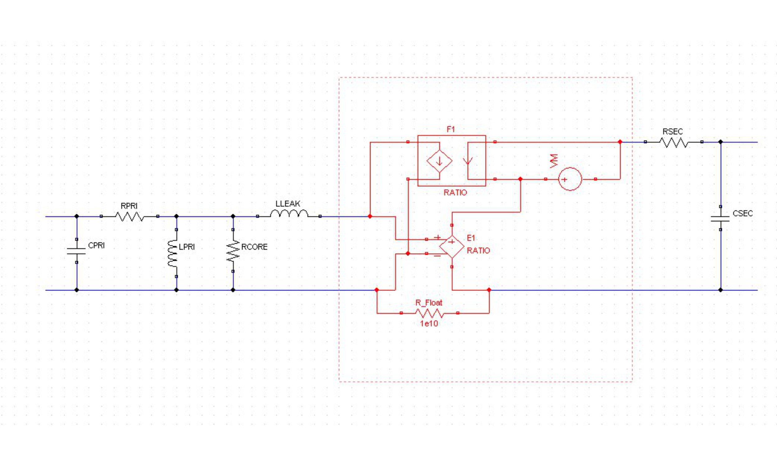
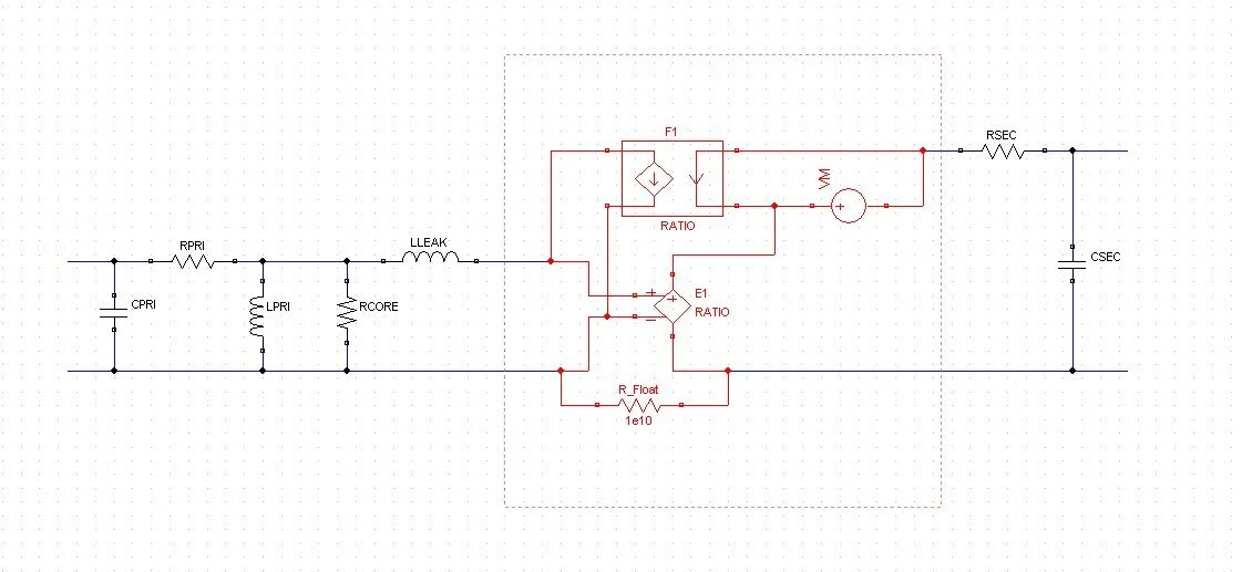
What We Did: Transformer Modeling
Because the connection to Foundation Fieldbus is (much as with Ethernet) a transformer, we needed an accurate model of one of those, too, that could be imported into our other SPICE models.
And unfortunately, over the years increasing numbers of transformer manufacturers have dropped those parts of their product lines specific to Foundation Fieldbus. There’s just not as much money in making them as there is in making transformers for Ethernet. So devising a new PHY layer today means finding the audio transformer that can pass the signals required. (Ethernet transformers are wound to frequency cutoffs far too high for use with the lower-bit-rate signalling on Foundation Fieldbus.) That means making “black box” measurements of the transformers that might work (since you’re doing an “off-label” implementation when you’re not using them for audio) and then feeding those data into a relatively sophisticated transformer model.
Any device with two coupled inductors in it is bound to have a relatively complex model, with parasitics and leakages to include. We came up with a model that struck a good balance between being understandable, accepting data we could get with “black box” measurements of real devices (since the manufacturers generally weren’t doing this), converging quickly in simulation, and producing results accurate enough to design to them.
What We Did: SPICE Simulation
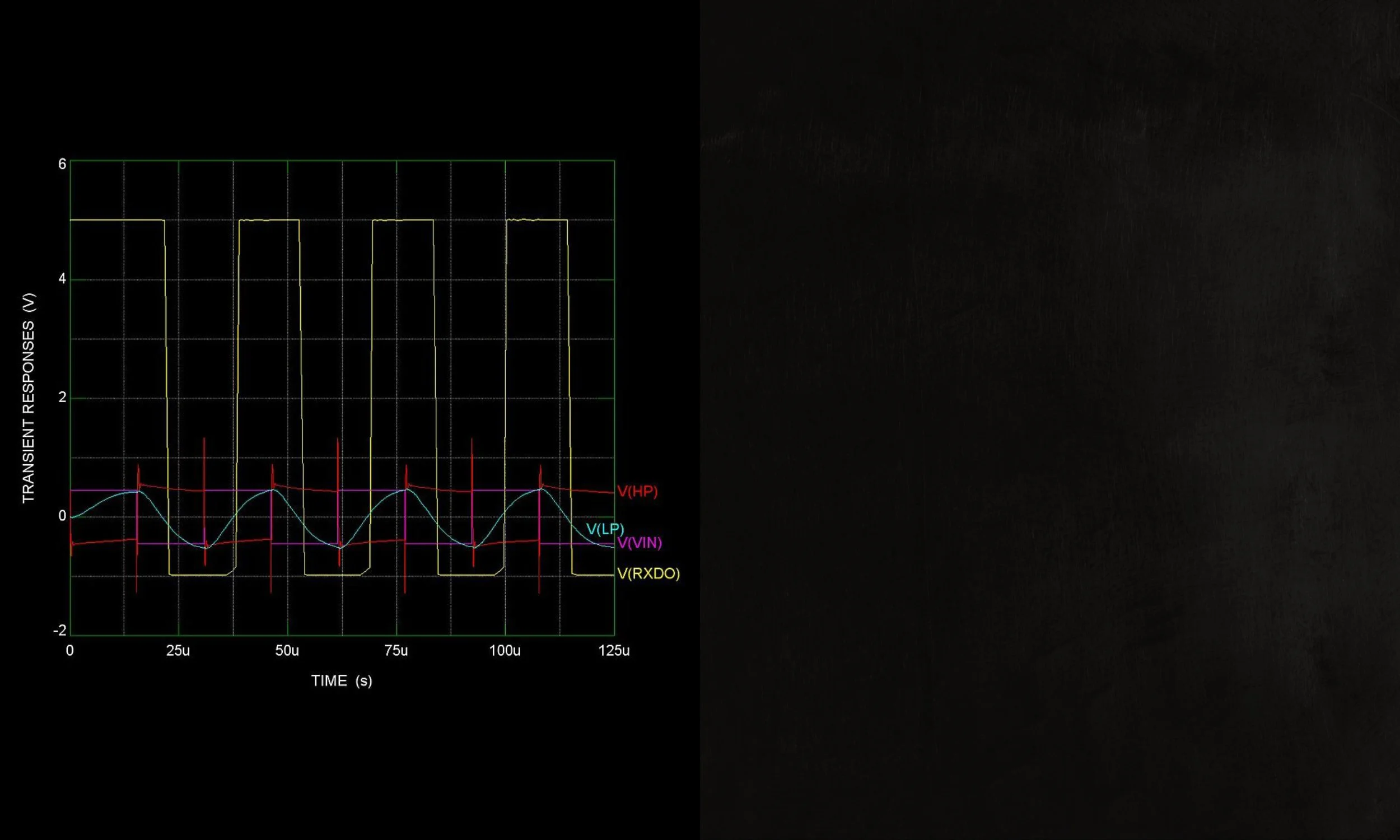
We modeled both transmit and receive signals on the bus to be sure they met specifications and were recoverable. Here is a set of traces of signals on the line after being sent through a transformer, being lowpass filtered for noise immunity, and being converted to a logic pulse train by a comparator with hysteresis.

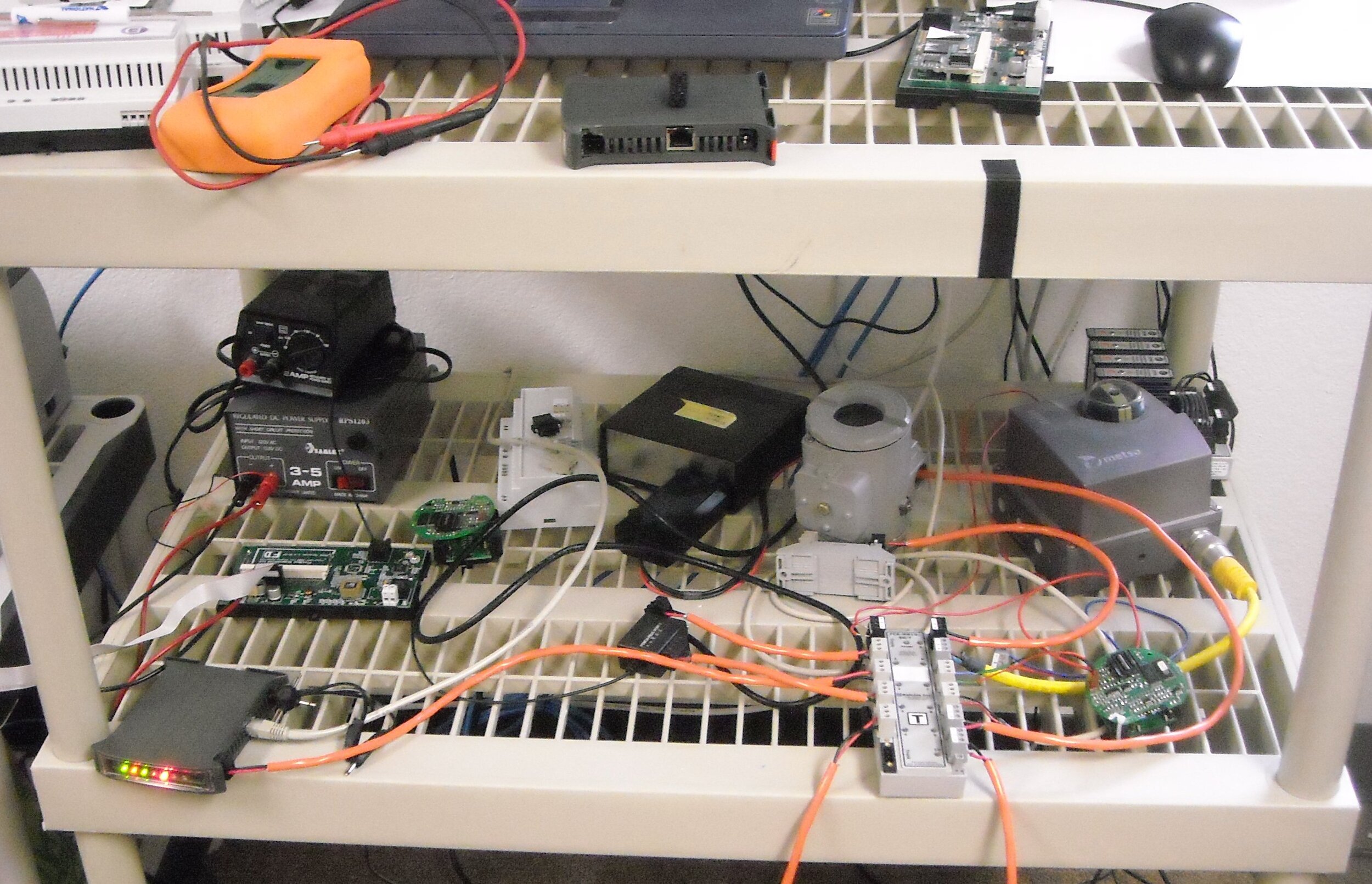
What We Did: Testing the System
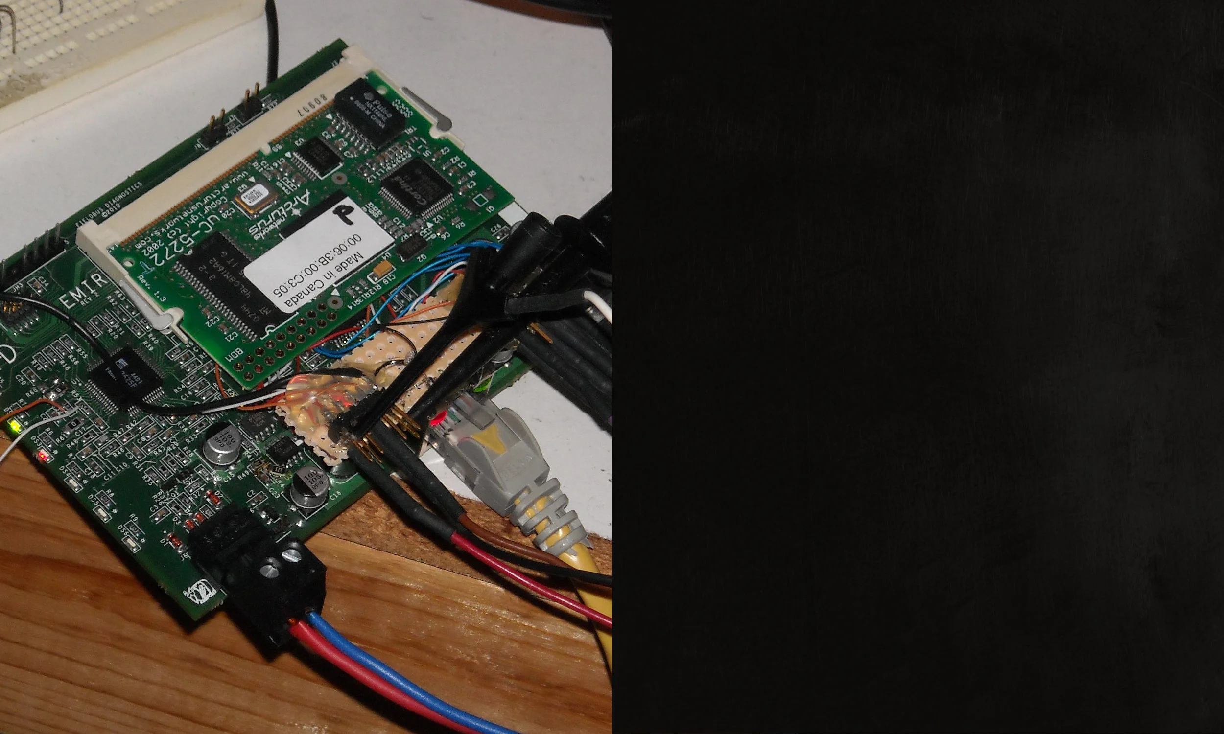
Our design implemented a PHY layer, power supplies (buck-boost converters) to power the device from the DC voltage on the bus, and enough programmable logic for the outputs of our Fieldbus-specific design to be sent to a small embedded microcontroller board made by Arcturus Networks for protocol disassembly. We also implemented an Ethernet PHY layer that attached to the Arcturus board in order for it to serve web pages containing protocol information to a local area network.
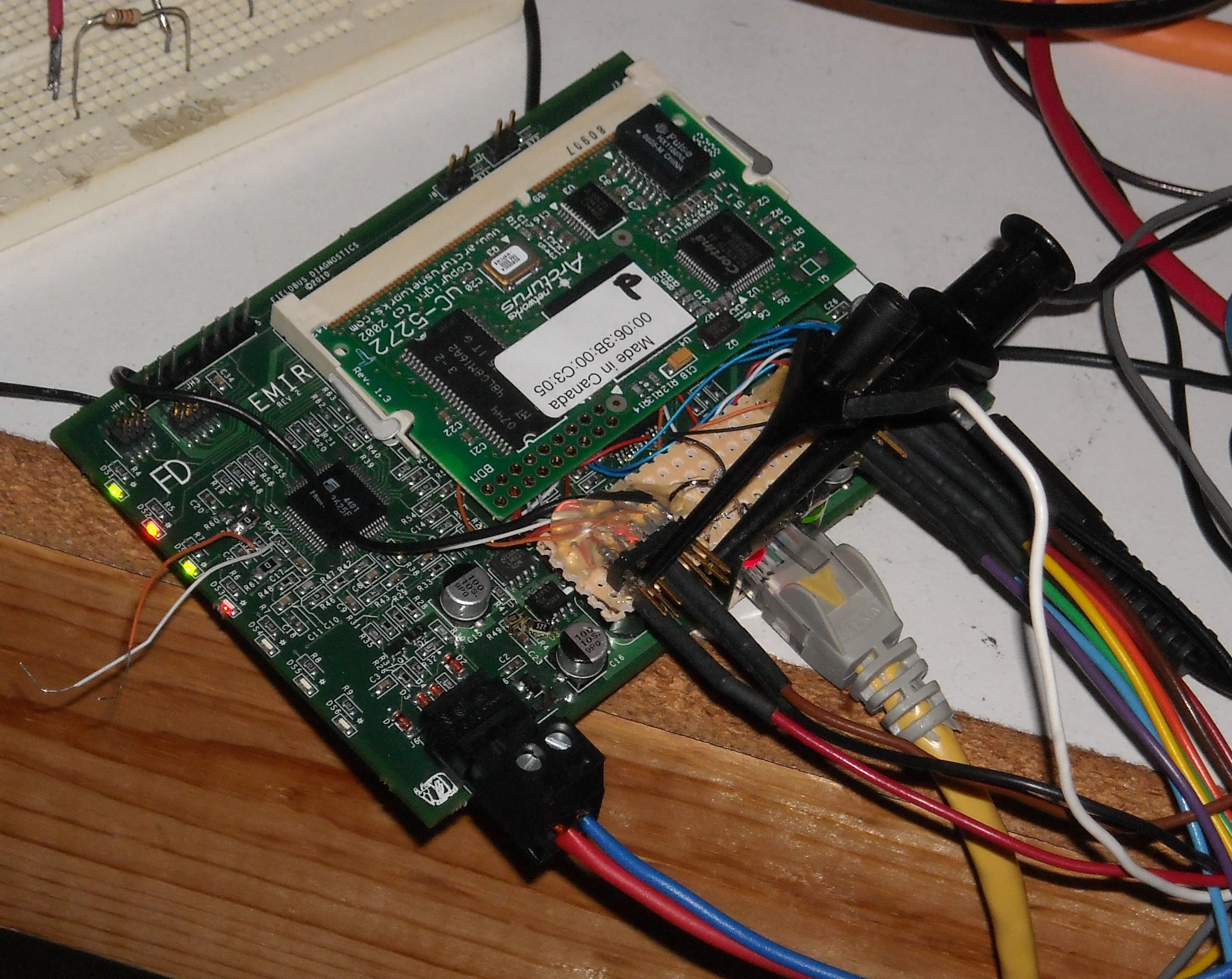
What We Did: Testing the System
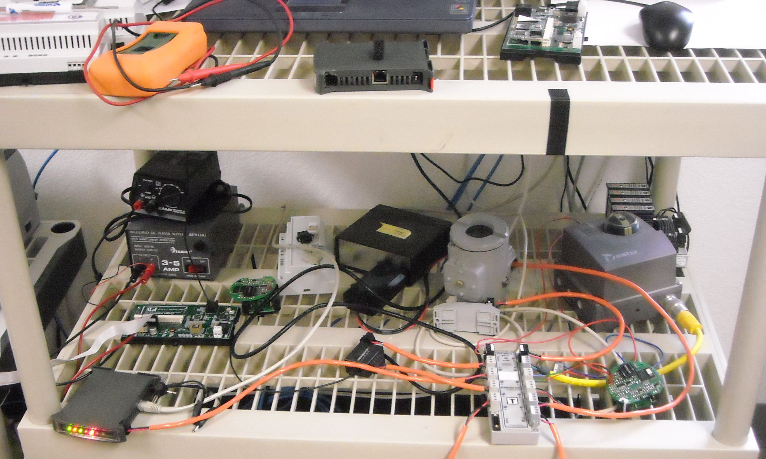
After doing some basic testing of the PHY layers (Fieldbus and Ethernet) on our board, verifying the switchmode power supplies from which we got our power off the DC voltage impressed on the bus, and checking out the programmable logic that connected our PHY layers to the I/O of the embedded Linux board; we put it all together in a Fieldbus network with a lot of different kinds of devices attached. The goal there was to verify that it all played together properly, no device got in another device’s way, and we got full protocol disassembly for all devices — which was key to being a usable piece of test equipment.
And our customer, who did the protocol disassembly software, came away saying, “We can see it all thanks to your design.”